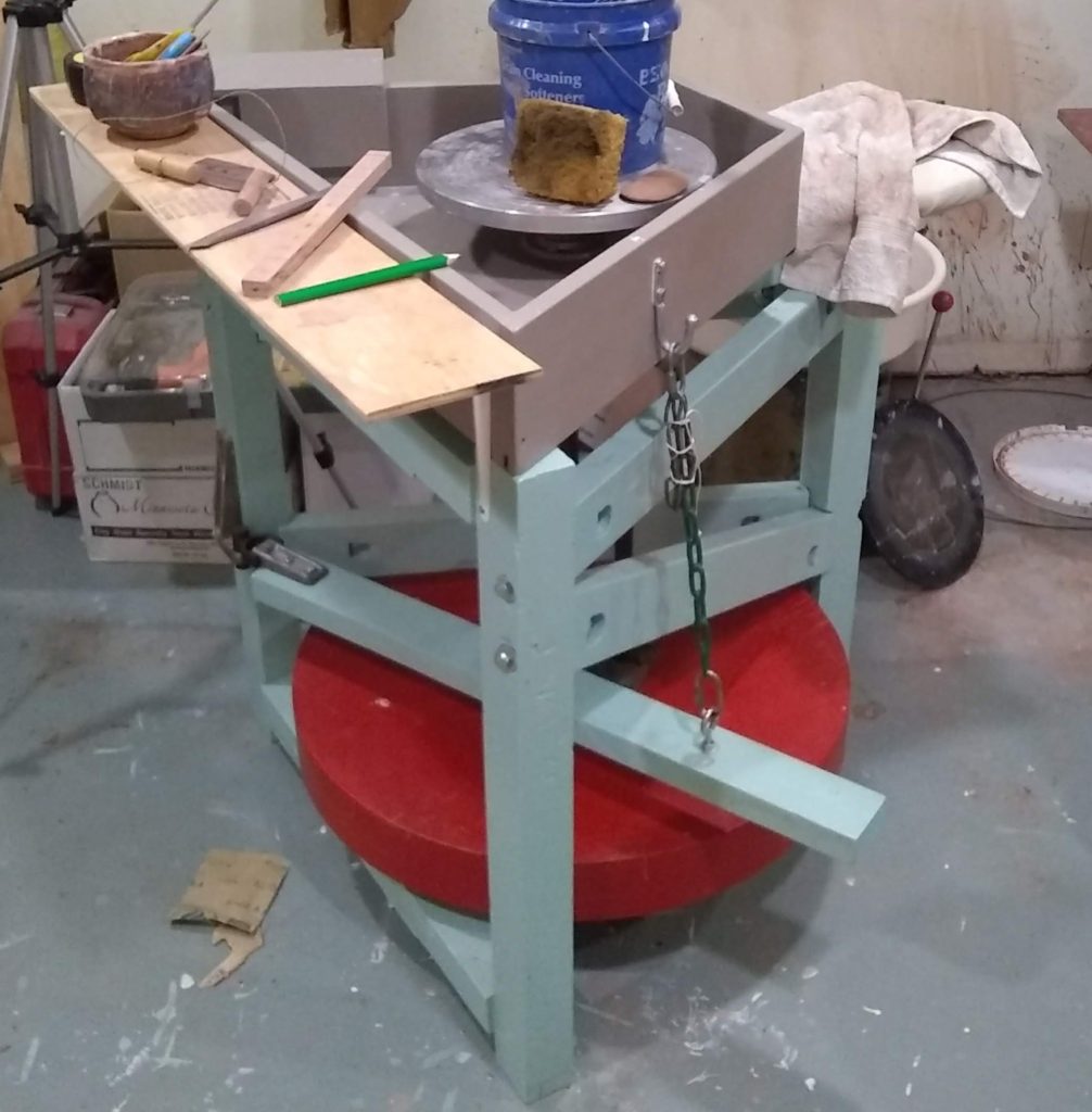
Hi fellow potters and enthusiasts! I am so excited because I have finally made my dream pottery wheel. And this is no regular kickwheel like the standard kit Brent has–it’s a Leach style treadle wheel! Woohoo!
First things first. This is not some masterful piece of ancient Japanese joinery using zero bolts or screws. This wheel is also not made with perfectly hand-chiseled joints pristinely cut with no splintering where the chisel was used. But you know what? It is a very solid wheel, and an absolute pleasure to use. The crank turns well, the flywheel spins smoothly, the tray is removable, and I even added a one-of-a-kind drink shelf that can easily be moved around to where I want it at any time.
You’ll notice that it’s painted. Yup. Did I cover up that precious wood grain that so many fawn over? Yup. Do I feel the slightest remorse for doing so? Nope. It is painted in fun colors, colors that give me inspiration and a fun attitude when I am about to be making pots, and I find that important. The colors were actually inspired by the Icee machines you find at Target or gas stations. You know, the polar bear with the sweater on. That one. Anyway, paint is formulated so well these days that the protection you gain from painting raw wood is really superb. It is wipeable, wear-resistant, and gets harder as it ages. It can always be repainted a different color or another coat added on in the rougher wear areas. It dries fast and is easy to apply and makes things look good. And it’s cheap. Sweet!
I used simple, cheap building materials. I engineered the plans so that I could use just one sheet of plywood to make the flywheel. I learned how to chisel stuff, and how to sharpen a chisel (this is super important). I got over my fear of bearings, specifically if they would hold the assembly up with just those set screws (they do and it works marvelously). And most of all, I had a really great time meddling around building this thing, getting over certain fears I had about not having all the skills necessary, and dreaming of the type of pot I would be able to make after it was finished in its wonderful, gleaming state of fresh paint.
Well, at long last, here it lies in all its glory. Pardon the messy basement studio.

the leach treadle wheel 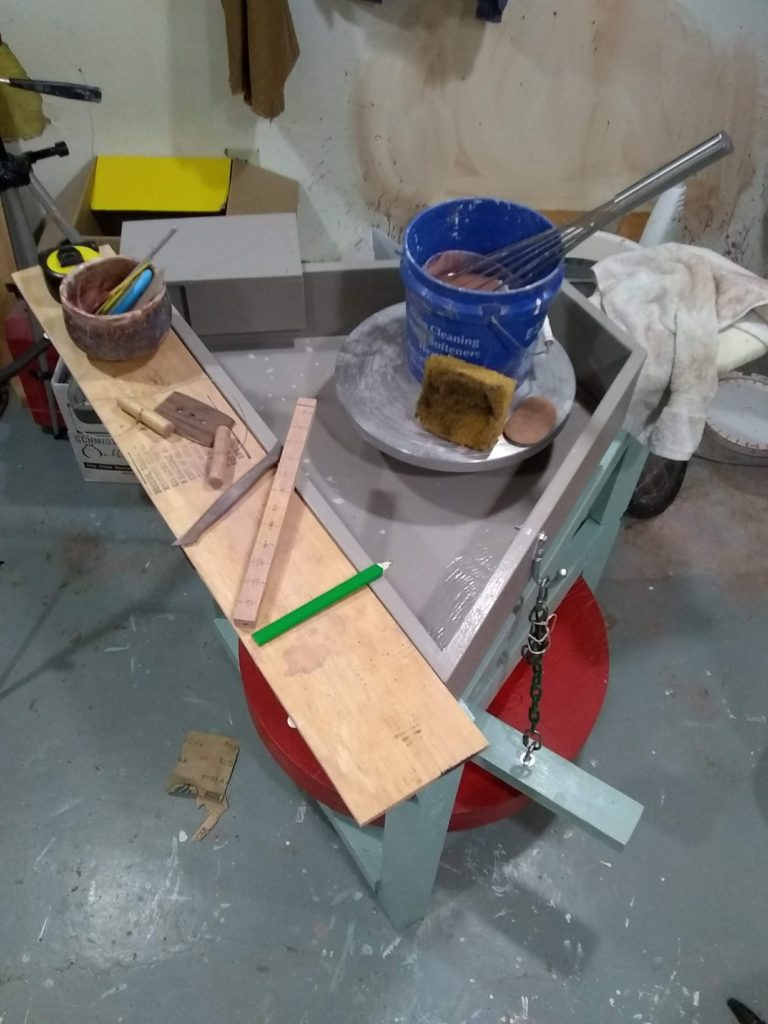
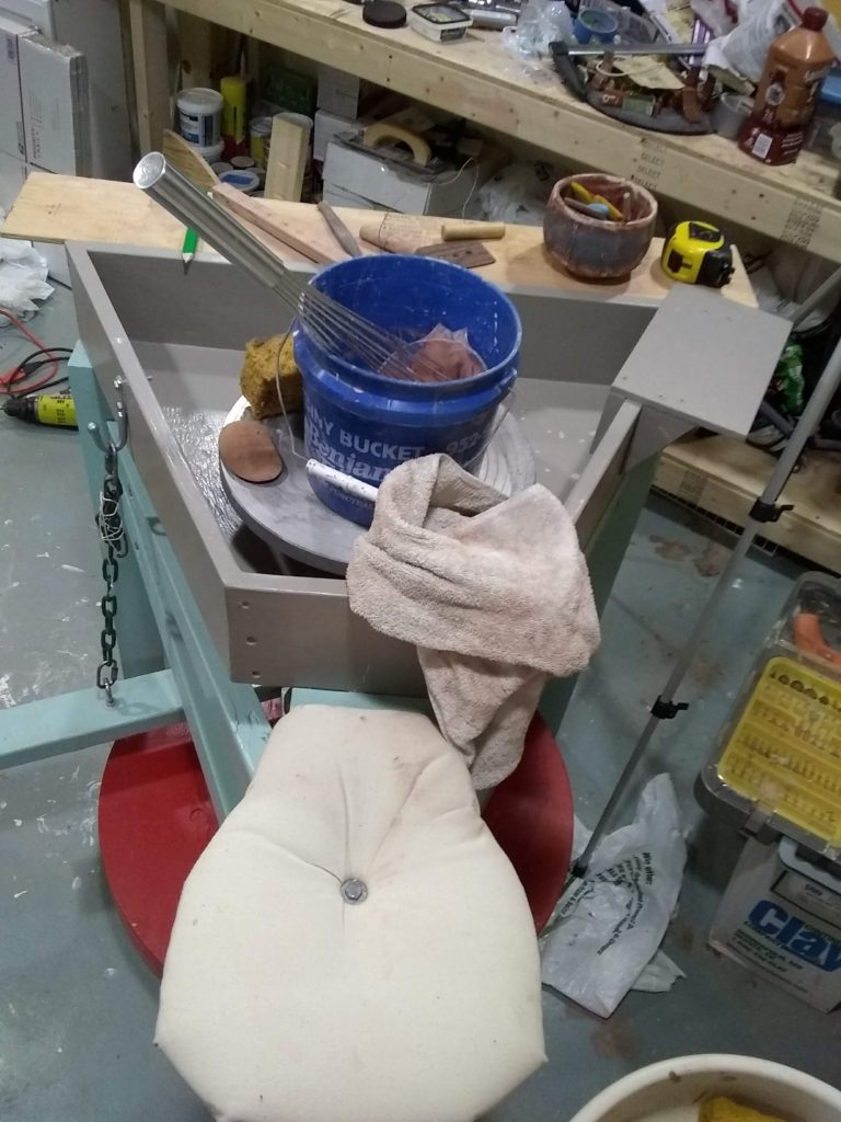
view from the seat. notice the removable drink shelf! 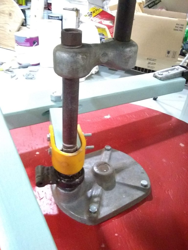
crankshaft with kids plastic swing seat piece–no leather belt here! 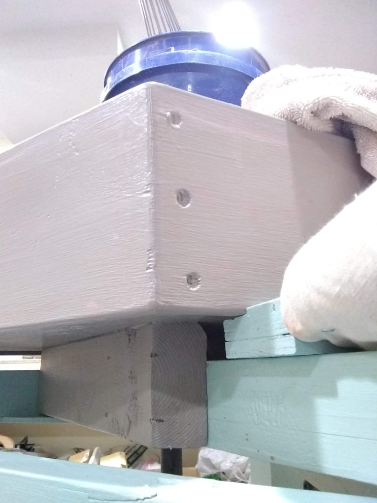
box angles 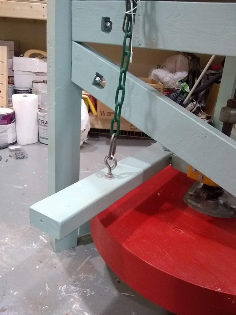
treadle bar with swingset chain 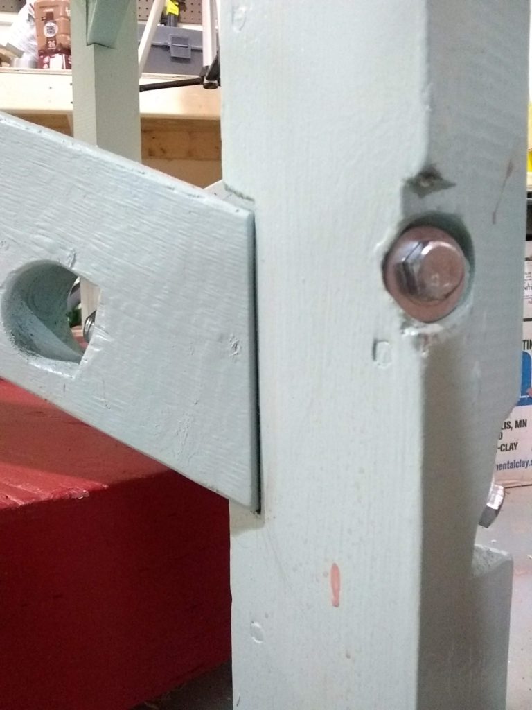
good-fitting joints with long bolts to secure 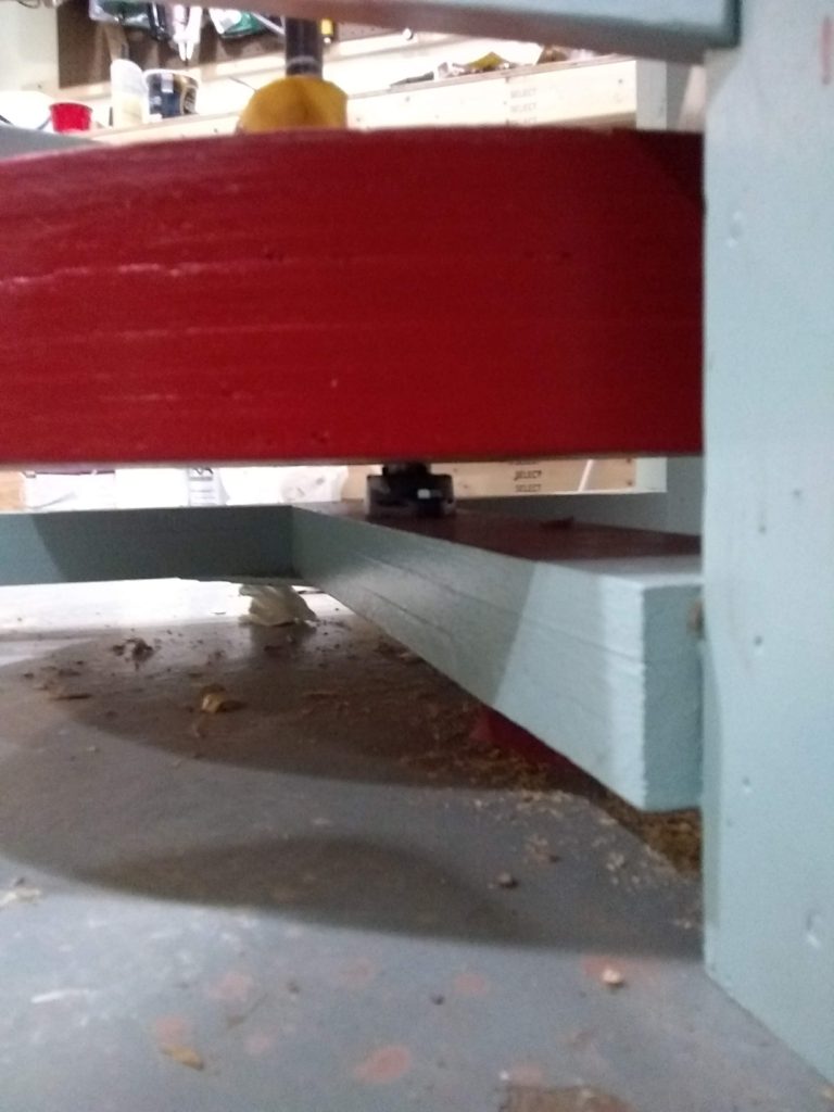
under the flywheel. here is the second bearing. 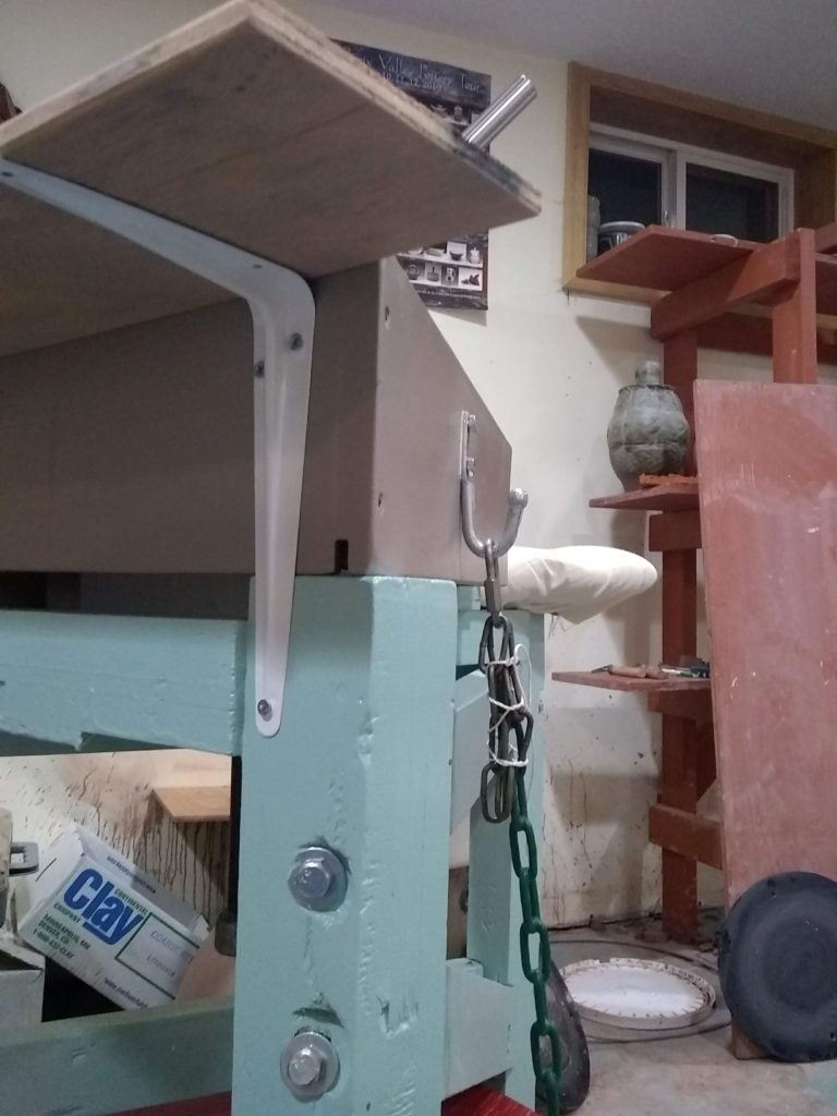
chain hook and pot shelf brackets 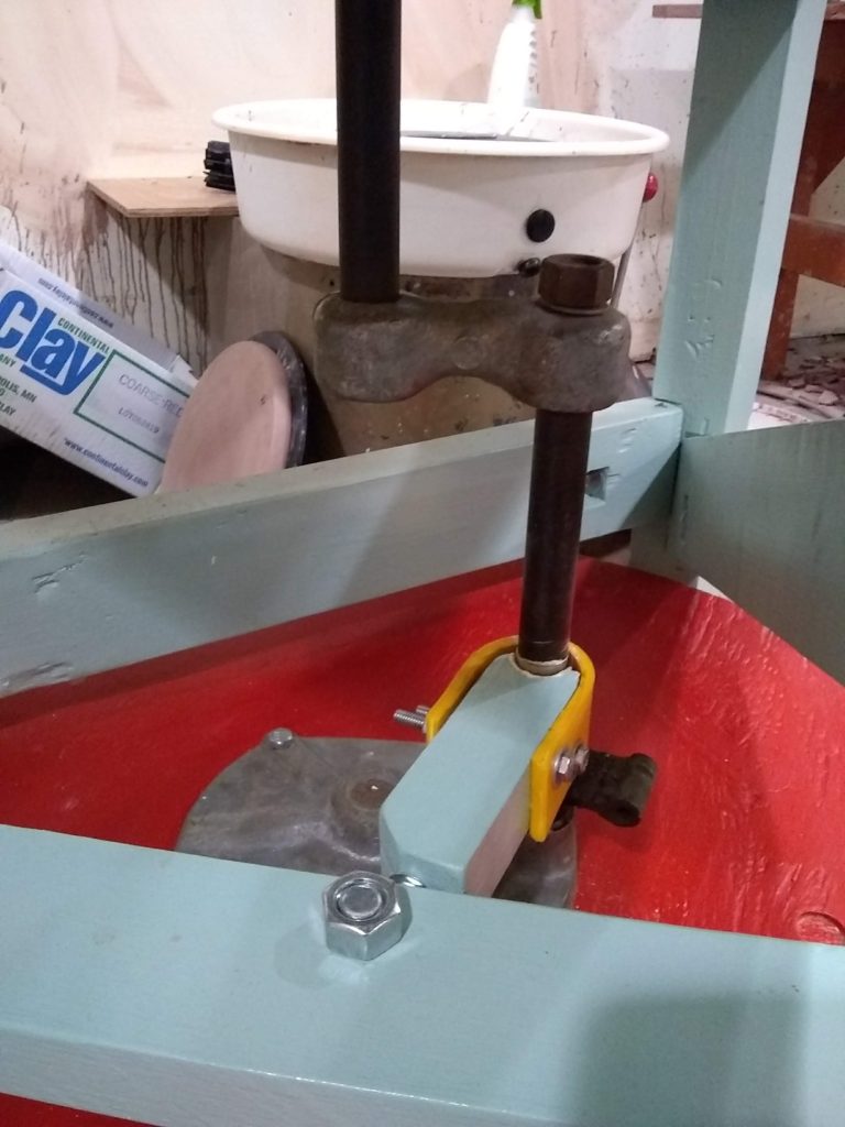
crank mechanism 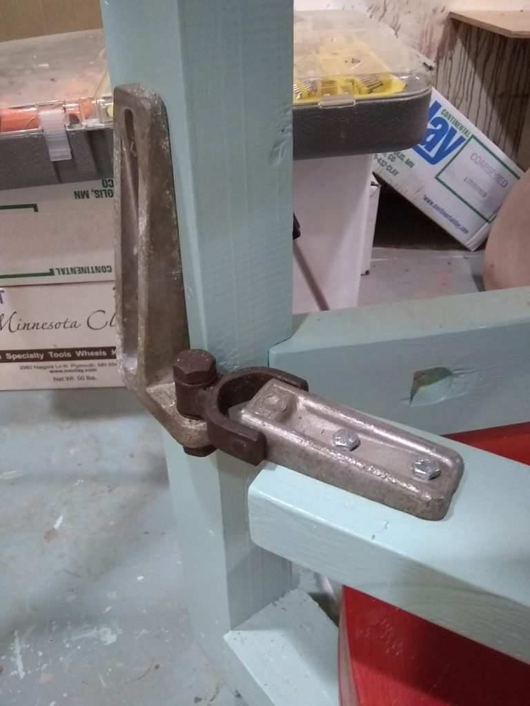
treadle bar joint, adjustable 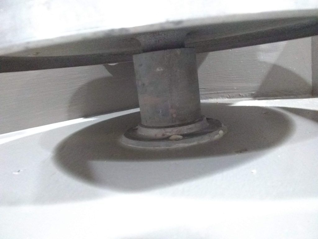
under the wheel head
Hi ,looks great
I am looking forward to make myself one ,
This looks fabulous ,
congratulations
Hello Meir,
Thank you for the comment and kind words. I can’t encourage you enough to build one, they are a sweet wheel. You can do it! And don’t forget to measure your doorways so you don’t build it outside and realize you can’t get it through the doors. If you need help, let me know!
Phill
Hi. May I ask a question?
Hello Teomanas,
Of course you may ask a question. Please do!
Phill
Hey Phill – awesome machine! I really want to build one of these but am unsure of how to construct the crankshaft mechanism and the weight and dimensions of the fly -wheel? Would be grateful for any info thanks – Dom
Hi Dom,
Thanks for the query.
The crankshaft is a 1″ solid steel bar, with an offset crank about 3″ on center. Get 2, 1/4″ or maybe thicker steel plates, drill two 1″ diameter holes in them 3″ apart on center. The lower plate will need to be larger than the top because you screw lag screws from that bar down into the flywheel to attach the flywheel to the shaft mechanism. The lower plate should have maybe 4-6 holes that will accommodate lag screws, so plan for that. The height of everything is dependant upon everything else, so you’ll have to just draw that up. I would have the offset crank part maybe 10″ long?
To assemble, put the solid bar through both plates, leaving enough on the bottom to accommodate the flywheel and space to add a flange bearing.
Slide another 1″ steel bar through the other two holes. Come to think of it, you might not need holes in the steel plate for the offset crank bar, you probably could just weld them right to the plates top and bottom. Anyway, what I’ve heard is that it’s important to weld the main shaft all the way through, and then the offset part afterward. Then you cut the main shaft off in between the offset crank area after everything has been welded together.
A friend of mine gave me the metal pieces for my wheel and part of the frame, so my job was a bit easier than starting from scratch. Look up Andrew Holden’s book self reliant potter, it gives decent instructions on there and some pictures. I bought the book online for maybe $15 used, well worth it.
The flywheel i made from 3/4″ cheap plywood (not osb or particle board though). I used 1 sheet and got creative cutting partial rounds wherever i could to get I think 5 rounds total. This got my flywheel to be almost 4″ thick. The flywheel was the standard 28″ width, but honestly just cut the plywood into 2×2′ squares and then cut out 2’wide rounds. Then you have way less waste and it will be much easier. You can then make your flywheel thicker, as long as you plan that in to your crankshaft plans.
My biggest mental hurdle was how the crankshaft was held up. It’s actually very easy, but sounds precarious. Flange bearings have set screws. The whole crankshaft, flywheel, and wheelhead assembly is held up by two scrawny set screws, one for each bearing. But they hold up and work great, no problems at all. I was thinking about thrust bearings and all sorts of crazy things, but the set screws strangely work great. I bought my bearings off Amazon, you don’t need expensive ones. I think mine came in a two pack and they were maybe $25 total shipped. I bought 2-hole bearings (two holes for two lag screws to mount the bearing) and they might be called something else other than flange bearings.
Nice job! Growing up in England, I used these wheels quite a bit. Oddly though, all the ones I’ve used (all made in the 60s) had cast concrete flywheels. About 2-3″ thick, and probably the standard 28″ in diameter. Takes a fair bit to get them going, but once they’re there, it’s a piece of cake, and you can really ease off for things like the rim. One thing it’s worth remembering is that Leach and the Japanese potters he followed (and most other Eastern potters), throw off the hump from a piece of clay that is often 10-15 pound, another extra weight for momentum.
Hi Robert!
Sorry for the hiatus, but we moved and it has taken longer than I anticipated to get back into the swing of things.
Thanks for the point about the 10-15 pound lump, that would help! I think because I typically throw individual pieces from individual lumps, that I should add a bit more weight. Those cement flywheels sound HEAVY! Much like a Lockerbie or standard Continental-style wheel I suppose. I don’t mind the lack of weight too much yet, but perhaps someday I will add some to see if I like that better.
Thanks for the kind words Robert! I appreciate the comment and compliments.
All my best,
Phill
Thanks for the information Phill – that really helps!
I have all materials already. Wood or metal. And I found some plans for original Leach wheel. Just I wonder, On the same structure, can we add a motor system also? is there any sample for this? not plan but someone did it in the past? For example, when there is no electricity, aparting it from the shaft somehow and going to work with pedal. is it possible or practicle in your opinion?
Hello Teomanas, and sorry for the late reply. I believe adding a motor would make the wheel less fun, and would be a difficult task to do. You don’t need a motor, it is quite easy to keep the wheel spinning no problem. Using your leg muscles allows for imperceptible adjustments that a motor just cannot do. It also gives the pots a different kind of life and vibrance, as if they dance. My opinion is that adding a motor would be a detriment rather than an aid.
Re: If welding shaft assembly, you’ll have a wonky / off-centre wheelhead 2-3mm caused by a slightly bent shaft, but can get it perfectly centred! I’ve made 1 wooden and 4 steel frame Leach style kick wheels. Got the wheelheads spinning perfectly centred with zero wobble.
Use 1″ round BRIGHT STEEL (better quality) shaft, not black steel. Because you’ve used heat to weld, the heat will have bent the shaft. BUT THAT’S THE KEY – BEND IT BACK USING HEAT. Do the following:
1. Remove wheelhead.
2. Set up a piece of wood or steel rod very close to top of shaft so when you spin the shaft you will see a wobble in the shaft. Rotate shaft slowly to see which side the shaft is bending. Mark it.
3. Rotate the shaft to put the bend 180 degrees away from you.
4. Apply heat for 1 to 2 seconds (AND COUNT) to your side of the shaft just beneath the slip tray. Use a no.1 oxy tip (preferable), or an arc welder (not ideal but it works) which I used.
5. Let it cool. Re-measure with the rod to see how much the shaft has corrected.
6. Repeat with the heat until the shaft is drawn back to perfect centre.
7. If you’ve done that and it works, surreptitiously slip into the conversation with your friends that you know how to straighten steel to zero -:)
Note: If bend is correcting too slowly, apply heat for a few seconds longer – BUT DON’T BLAZE AWAY OR THE SHAFT WILL OVER-CORRECT AND YOU’LL BE BACK TO SQUARE ONE.
Hope this helps. Cheers. Andrew.
Hi Phillip. Nice wheel you’ve made. Can’t beat throwing a pot on a Leach style kick wheel. So peaceful. A question about your wheel – do you get a knocking sound on rotation coming from the shaft assembly? Cheers. Andrew.
Hello Andrew, yes I get a sort of knocking sound, like the classic treadle sound if you will.
Re: Stopping Knocking Sound. Hi Phillip. Sorry I haven’t replied sooner. Thought I might get an email to show my question was posted. Not so, but moving on. This is about the knock/slap sound you’re getting. You get a knock/slap and Simon Leach’s wheels too get knocks/slap. It can be fixed entirely, as I have done. My wooden wheel has traditional set up which is same principle as yours. The knock/slap is coming from the connector from the kick arm to the shaft. On the Power Stroke/push it’s fine, but on the Return Stroke the knock is coming from the hard metal shaft hitting the hard wood of the connector. To eliminate it, wrap leather or similar to the connector (which is on the other side of your yellow piece of plastic?, Phillip.) so the shaft is slapping the wooden connector wrapped/covered with leather. The slap will be gone. It has a little more friction or drag, but a few drops of oil occasionally on the leather will lubricate well, and beats the hell out of a “classic” knocking noise, as you describe it. The link photo (go to bottom of link page for photo of my wheel) shows brown leather on the connector on BOTH SIDES of the shaft. Go to
https://www.tradingpost.com.au/Hobbies/Other-Hobbies/Pottery-Kick-Wheel-New/Rosanna/VIC/AdNumber=4B2LRC Hope this helps someone. Cheers. Andrew.
Ha! What a genius idea! I will have to build that into the next piece. Very cool, thank you!
Re: Creaking and Twitching-how to fix. Wooden frame Leach style wheels creak and twitch, unless the mortise and tenon joints are made by a master. The wooden wheel that I made was made with recycled wood. It creaked and twitched, but I fixed it. It’s now solid as a rock. To stop the twitching and creaking, I welded up 4 heavy duty right and braces and fixed them to frame. I then made and sold 4 metal framed wheels. No twitching or creaking. But I had a very well made factory made steel frame wheel and it twitched. It was a great wheel, but shows how hard it is to get a rock solid frame. I saw an excellent wooden frame wheel destroyed by a really athletic potter. The frame didn’t stand a chance. It then needed bracing to fix it. A fix can be done. Hope this helps. Cheers. Andrew.
Have you seen Woodley’s newest wheel? It is hidden away on their website somewhere. But the pictures show some bracing I believe. Or maybe that was Simon Leach’s wheels made by the Amish. I might be getting the brackets confused (after looking at all sorts of treadle wheels for so long!). I imagine those brackets would really strengthen the joints. Warren Mackenzie threw on a really old treadle that was not bolstered and he did this for many years, so they do hold up for a good amount of time. Thanks for all the advice and help and comradery. Cheers Andrew!
Meant to say above “right angle braces” 🙂
Hi people. Stand-up kick v Sit-down kick wheels. When I was 19, I bought a second hand stand-up kick wheel. I learned to pot on it. Then one day a friend invited me to use his Leach style kick wheel. As soon as I started on it, I was converted. It was so impressive in many ways – comfort, ease of throwing a pot, and it just felt so right. Where I now get my pots fired, it’s all electric wheels for customers to use, and nobody seems to know anything about Leach kick wheels let alone having used one. It would be great to see them get one Leach style wheel. I’m sure others would be converted in an instant, as I was, if they had the chance to use one. As for potting on an electric wheel, it’s just not the same. I can understand using electrics for volume production. It’s interesting, Phillip, your wheel looks so similar to the my friend’s wheel. Anyhow, all this talk is getting me in the mood to go out and throw a few pots. Cheers everyone. And.
…oh, and about the bracing you mentioned Phillip, I think I saw one of Simon Leach’s videos where there is a brace or two installed. Will have a look. Cheers Andrew.
Well done this is impressive!
I have an old Leach kick wheel without a wheel head (tapered spindle) can you suggest where I might obtain one?
I am sorry Gillian, I am uncertain where to get a tapered wheel head. I would search used Leach wheels and look for parts. Perhaps an art center has an extra one they can sell you? Or you could get one made. Maybe a machine shop/welding shop can cast you a wheelhead and carve out the matching hole for it? Definitely try more rural welding shops, not city-based ones–those will not be looking to get small jobs like yours and they will either make you pay a ton more than its worth or will just say no.
Have you found a wheel head yet ?
I can supply one from New Zealand .Our Leach wheels were made under license to Bernard Leach and I have used mine for over 50 years.
They were made by Seadboard Joinery and are I feel improved over the Woodley.
I have repaired…restored many of them and I have a few spare Morse taper wheel heads.
The NZ wheels used cast iron…. Much nicer on the finger tips.
I can sell and post one.
Good luck Renton Murray
Just found your site. Great job on wheel! Did you use 3” x 3” for legs as listed in Leech’s pattern or the 3 3/4” x 3 3/4” (nominal 4” x4”) as purchased sizes really are.
Hi Amg, these legs were closer to 3″x3.5″. They were 4 sandwiched 1×4’s glued up together. You could definitely use the nominal 4×4 size, this will not affect making the frame with any more difficulty. You can even use pine, like a douglas fir. Just know that pine is a bit softer and will compress a bit on the tight areas, so those will need to be tightened occasionally. Also use some wide washers in order to limit the compression with the bolts.
Working on building one now. Thanks for your video and insights. What is a good fly wheel weight ? Currently my build is a at 66 lbs made of MDF and PLY. 30”x 4.5”. Do I need more weight?
Hi Steve,
I wouldn’t go any heavier. Mine are at about 40 lbs. I used 3/4″ plywood cut into rounds and glued together. They were the perfect weight I think, and probably what most of the potters use on Treadle wheels.